Hybrid Electric Vehicles have gained increased popularity in recent years as consumers look for alternative fuel vehicles to conserve energy and reduce CO2 emissions. Electric motors are more energy efficient than conventional combustion engines running on gasoline, and they can dramatically reduce emissions. While batteries are at the heart of HEVs, they are also the source of many barriers to adopting HEVs because of reliability, safety, weight and cost. To overcome these barriers, battery monitoring systems are employed to maintain longevity and safe operation of the batteries. Due to their high operating voltage, sophisticated isolation techniques are required. Baoxing Chen, Sr. Staff Engineer, Analog Devices, USA
There are a couple of major challenges for designing the battery monitoring systems (BMS) because the battery stack voltage can be as high as 400V in many HEVs. This high voltage is needed to deliver enough power to the motor, but it creates a problem for transmitting the state of charge (SOC) current and voltage signals from the battery cells to the microcontroller that processes the information from all cells to maintain safe operation of the battery stack. To get around this hurdle, BMS employ galvanic isolation to transmit data from the high voltage battery to lower voltage electronics elsewhere in the vehicle. Traditional isolation solution such as optocouplers are not ideal for HEV because they degrade over time, especially in automotive environments where high ambient temperatures are expected; they also do not have enough bandwidth to handle the high speed Serial Peripheral Interface (SPI) that is typically used between the battery monitoring ICs and BMS microcontroller.
The other major challenge is to achieve power isolation in addition to signal isolation in HEV BMS. Hardware protection system needs to be in place to provide isolated power on the battery side, so that the isolators can pass safety information such as over-voltage information to the microcontroller to shutdown the system appropriately in the event of hardware failure. The safety information needs to be uninterrupted, even if there is a hardware error where no battery power is available to power the battery monitoring ICs.
The novel iCoupler digital isolators with isoPower provide signal and power isolation using on-chip transformers. Magnetic coupling allows for signal transfer across isolation barrier and iCoupler devices consume much less power compared to the optocouplers. Integration of multichannel and digital interface makes them very easy to use and it leads to significant reduction in component count and board space. The device performance based on magnetic coupling has no wear-out mechanism and has little variation over time and temperature.
iCoupler technology with isoPower
The micro-transformers used in iCoupler devices are stacked windings built on top of CMOS substrates, and they are manufactured using standard semiconductor processing. The polyimide films sandwiched in between top and bottom coils of the micro-transformers are deposited at wafer level and provide well controlled thickness and high structural quality. The cured polyimide films used in iCoupler devices have dielectric breakdown strength over 400V/μm. With a total thickness of 20μm between coils, the polyimide layers enable the devices to be able to survive over 8kV instantaneous AC voltage. Because deposited polyimide films are free of voids and do not suffer from corona discharge, iCoupler devices also exhibit good aging behaviour and work well under continuous AC or DC voltages. The polyimide has also very high thermal stability. Its weight loss temperature is over 500°C, and its glass transition temperature is about 260°C.
The transfer of logic signals across isolation barrier is realised through appropriate encoding at the primary side and decoding at the secondary side to recover the input logic signals. Specifically short pulses around 1ns wide are transmitted across the transformers with two consecutive short pulses to indicate a leading edge and a single short pulse as a falling edge. A non-retriggerable monostable at the secondary generates detection pulses. If two pulses are detected, the output is set to HIGH. On the other hand, if a single pulse is detected, the output is set to LOW.
For transmitting power across the isolation barrier, these micro-transformers are switched resonantly to achieve efficient energy transfer, while the energy regulation is realised through a low frequency PWM feedback signal, which controls the duty cycle that the high frequency resonant action is left on. Both the transformer switches and Schottky diodes used for rectification are implemented on-chip.
technology with
isoPower
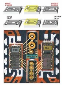
An example implementation of a quadchannel isolator with a fully integrated isolated DC/DC converter in a 16-lead SOIC package is shown in Figure 1. The left chip has high voltage CMOS switches and the right chip has the rectification diodes and converter controller. Two cross-coupled switches together with transformers form the oscillation and the Schottky diodes are used for fast and efficient rectification. The transformer chips are located in the middle. This implementation has the transformers on separate chips but, in principle, the transformers can be put on same chips for the switches or the Schottky diodes. For the top transformer chip, the two larger transformers are power transformers while the small transformer is for transmitting the feedback PWM signal. The bottom transformer chip holds four additional micro-transformers for the quad-channel isolator. The left chip and right chip also hold encoding and decoding circuit for the four-channel isolators.
Fully integrated half-bridge gate drives, isolated analogue/digital converters (ADCs) and isolated transceivers that are also needed for the isolation in HEV can be implemented similarly. Signal and power isolation provide functional integration that can dramatically reduce the complexity, size and total cost of the isolated systems for HEV applications.
Isolation for HEV battery monitoring systems
One of the major obstacles for the faster adoption of HEV is the additional cost, weight and safety concerns associated with the batteries that are required to drive electric motors. It is extremely important to monitor state of charge (SOC) and state of heath (SOH) of each battery cell. BMS is essential to ensure safe operation and maximum lifetime for the battery stack.
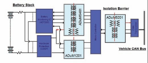
Figure 2 shows an example implementation of BMS in HEV. A battery monitor IC such as AD7280 monitors the SOC for the battery stack and communicates with the controller through the SPI interface. The SPI interface is isolated through ADuM5401, a fourchannel isolator with integral 500mW isolated DC/DC converter. Besides the battery monitor IC, a redundant hardware protection system is typically used to ensure the battery cell voltage is within the safe operation ranges. In the event of a hardware error, the hardware protection system will be able to communicate through a two-channel isolator, ADuM1201, with the microcontroller and shut down related system components appropriately. If the battery monitor IC requires more than five channels of isolation, other higher channel count devices such as ADuM130x and ADuM140x can be used. IsoPower plays a very important role here, as we need to make sure the system protection is in place, even though the battery power is not available. The 500mW isolated power can be used to provide the power for the hardware protection IC, isolators at the battery side, and also the power for the ADCs inside battery monitor ICs if there is no internal regulator from the battery terminal to power-up the ADCs.
If multiple battery ICs are needed, dedicated isolation for each battery stack can be implemented, especially when each battery stack has its own module. An alternative solution is to take advantage of daisy chain capability within battery monitor ICs such as AD7280 to pass the SPI commands across multiple battery monitor ICs without using isolation. Only the bottom stack battery monitor IC needs to communicate to the BMS controller through isolated interface.
The BMS controller also needs to communicate with other system controllers through the main vehicle CAN bus. ADuM1201 or ADuM5201 can be used to provide isolation in between the BMS controller and a CAN transceiver. ADuM5201 has the advantage to provide isolated power to the CAN transceivers from BMS controller.
Isolation for HEV motor drive
The most important elements are, of course, electric motors that make HEVs improve efficiency under certain driving conditions compared with an internal combustion engine. Its isolation needs are very similar to those in industrial motor drives. However, there are some unique requirements. The inverters used to drive the electric motors in HEVs need to be more compact, lower in weight, highly efficient and reliable. In addition, they need to be able to operate at elevated temperatures.
In a motor drive system for HEVs, there are two main parts of the circuit that require isolation. One is gate drive for IGBT of bridge inverters, and the other is motor phase current sensing. Phase current sensing provides IGBT device protection and linear current feedback information for the controller to maintain close-loop current control. Series shunt resistors, together with high precision ADCs at the inverter output, are typically used to sense the phase current. Isolated power supplies are needed to provide the bias for the current sensing ADC and gate drive circuit, and separated supplies are needed for each phase. The complicated signal and power isolation needs for the AC motor drives can be dramatically simplified with the use of iCoupler devices.
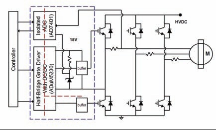
An example implementation for a low power motor drive is shown in Figure 3. The ADuM5230 is a half-bridge gate driver with integrated 200mW high-side 15V supply. It provides isolated 15V gate drive output for the high-side IGBT and another isolated 15V gate drive output for the low-side IGBT. Low-side isolation protects the controller from being damaged by the inductive switching transients coming from large IGBT switching. The 15V high-side supply, generated through an integrated DC/DC converter, provides power for the buffer circuit to drive the large IGBT, and it can also be used with a Zener diode to generate a 3 to 5V lower supply to power the current sensing ADC such as AD7401.
The AD7401 is an isolated second-order sigma-delta modulator that converts the analogue input to a high speed single-bit data stream that can interface directly with the controller. It receives clock from the controller while sending the clocked data stream back to the controller. Without an integrated ADC, multiple opto-couplers would be needed and slow opto-couplers are usually not suitable for transmitting this high speed data stream. Both the high-side gate drivers and the current sense ADC have their grounds referenced to the inverter outputs that can be switching very fast. iCoupler isolation with high common mode transient immunity is important to maintain data integrity for high-side switching and current sensing.
The red-dotted lines in Figure 3 are used to show the locations of isolation barrier, and the circuit components shown in the blue box can be replicated for bridge inverters for other phases. The inverter outputs need to be isolated from each other and multiple half-bridge gate drivers will achieve that. Each of the half-bridge gate drivers will generate its own gate drive signal and high side supply.
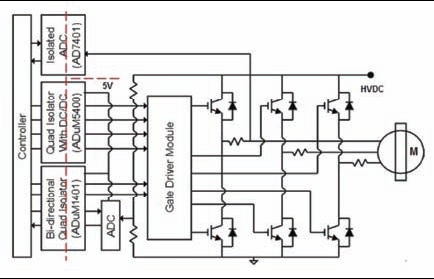
To achieve compact design, intelligent power modules are often used in HEVs. The HEV motor drive system implementation using intelligent gate drive modules are shown in Figure 4. The six gate drive signals are usually isolated through logic isolators, and they provide inputs to a gate drive module that provides further level shifting or isolation for the high-side IGBT devices. Logic isolation facilitates the communication between the controller and DC link ground, such as passing the DC link voltage or current sensing information to the controller.
Similar to ADuM5401, ADuM5400 is a quad-channel isolator with an integrated DC/DC converter that provides isolated power up to 500mW. It provides isolation for four of the six gate drive signals from the controller. ADuM1401, another quadchannel isolator provides isolation for the other two gate drive signals. The unused two isolation channels can be used for serial communication between the controller and a non-isolated ADC that can be used for HVDC voltage sensing, for example. The 500mW isolated power from ADuM5400 can be used to power up any logic circuits that are referenced to low side ground such as output side for ADuM1401, the ADC used for voltage sensing.
Conclusion
In summary, iCoupler technology provides robust isolation solutions for HEV BMS and electric motor drive systems. It eliminates many constraints from other isolation solutions. It provides a complete isolation solution in a single package, which significantly reduces the component count and system cost, simplifies the system design, and reduces the incremental design time. It makes HEV more efficient, more compact, lighter and more reliable.